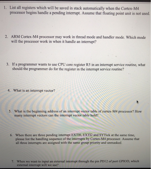
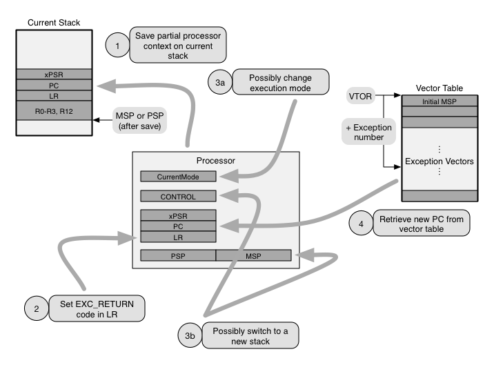
CortexM Interrupt Process (much of this is transparent when using C) 1 Interrupt signal detected by CPU 2 Suspend main program execution finish current instruction save CPU state (push registers onto stack) set LR to 0xFFFFFFF9 (indicates interrupt return) set IPSR to interrupt number load PC with ISR address from vector table 3DOCUMENTATION MENU DEVELOPER DOCUMENTATION Back to searchNov , 15 · modules' hardware consists of an ARM Cortex M4 host processor, Broadcom Annex A, Table A1, EN Requirements Table (ENRT) reproduced below as Table 1 herein Only Reference Items 1 through 9 are addressed in this report for Transmitters, since this report covers only the NFC Transmitter
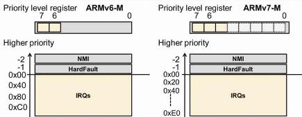
Arm Explains Good Interrupt Control For Low Power Processors
Cortex m4 vector table size
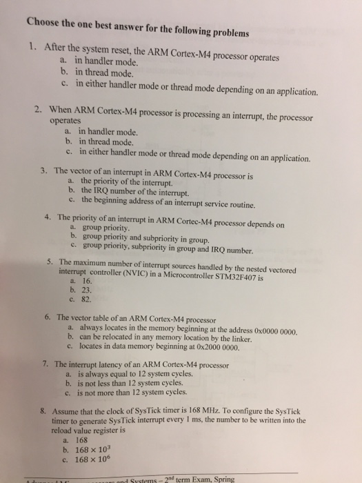
Cortex m4 vector table size-Most CortexM processors provide VTOR register for remapping interrupt vectors The following example shows a typical use case where the interrupt vectors are copied to RAM and the SysTick_Handler is replaced /* new vector table in RAM, same size as vector table in ROM */A 2 10 Answer the following short questions regarding the interrupt system of CortexM4 and Tiva C How many entries are there in the interrupt vector table?


Basics Of Porting C Code To And Between Arm Cpus The Cortex M1 And Cortex M0 Embedded Com
Aug 07, 09 · CortexM3 Interrupt Vector Table (via Embedded Freaks) bygreencn Leave a comment Go to comments In CortexM3, there are 255 interrupt vectors, and it's relocateable During the initial boot, the interrupt vector table are located at 0×00, but, then, if you want to, you can move it to somewhere elseSTM32 Cortex®M4 MCUs and MPUs programming manual Introduction This programming manual provides information for application and systemlevel software developers It gives a full description of the STM32 Cortex®M4 processor programming model, instruction set and core peripherals The applicable products are listed in the table belowThe Motorola processor has a 1024byte vector table beginning at h The first entry is the reset vector, which is at h This vector table also contains pointers to routines used by the processor, operating system, and users
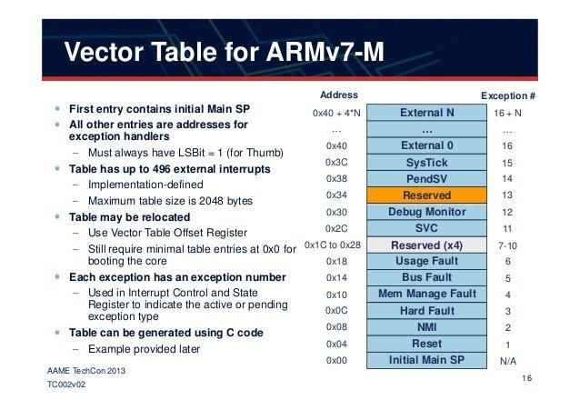
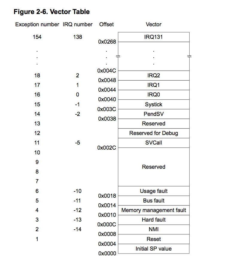
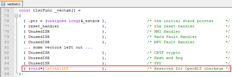
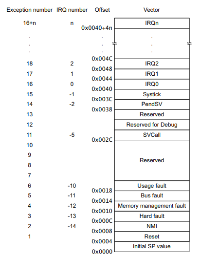
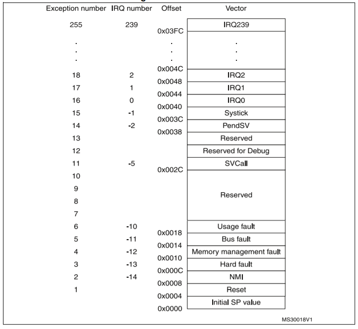
Aug 14, 16 · The 'vectored' means that it uses a vector table, shown for M0/M0 and M4/M4 below CortexM Vector Table (Source of images ARM) The table is 'vectored', because the 32bit entries in it (eg the Hard fault vector at address 0x000C'0000) point to the corresponding interrupt service routine for example the entry at address 0x08 'vectors' to the NMI interruptI was reading about the startup code and vector table of CortexM4 (STm32, Tm4c123) When I tried to find out the Vector table of NRF522 in the datasheet I couldn't find any I have searched the Infocenter and find out the NRF52 has three kinds of vector tablesSep 24, 19 · On the ARM CortexM4 the first entry into the vector table holds the initialization value for the stackpointer, which is automatically loaded into the CPU's stackpointer register upon reset After reset, the bootloader gets started first and, if a valid user program is present, it is the bootloader's responsibility to start the user program
Based on the Arm CortexM23 processor, the Corstone102 is targeted for use in small and constrained IoT applications Corstone1 The Corstone1 contains a reference design and system IP for building a secure System on Chip with the Arm CortexM33 processor Corstone1 is designed for mainstream IoT and embedded applications that requireCortexM4 Program Image • In the beginning of the program image, the vector table is located • Vector table holds the starting addresses known as exception vectors of all interrupts & system exception handlers • This includes the reset value of the stack pointer as well • In most applications, the vector table can be setup during compile time as a part of the application program imageSpecial note to ARM CortexM users ARM CortexM3, ARM CortexM4 and ARM CortexM4F ports need FreeRTOS handlers to be installed on the SysTick, PendSV and SVCCall interrupt vectors The vector table can be populated directly with the FreeRTOS defined xPortSysTickHandler(), xPortPendSVHandler() and vPortSVCHandler() functions respectively, or


Interrupt Vector Table An Overview Sciencedirect Topics


Sequence Of Interrupt Processing Steps Arm Cortex M Microcontrollers
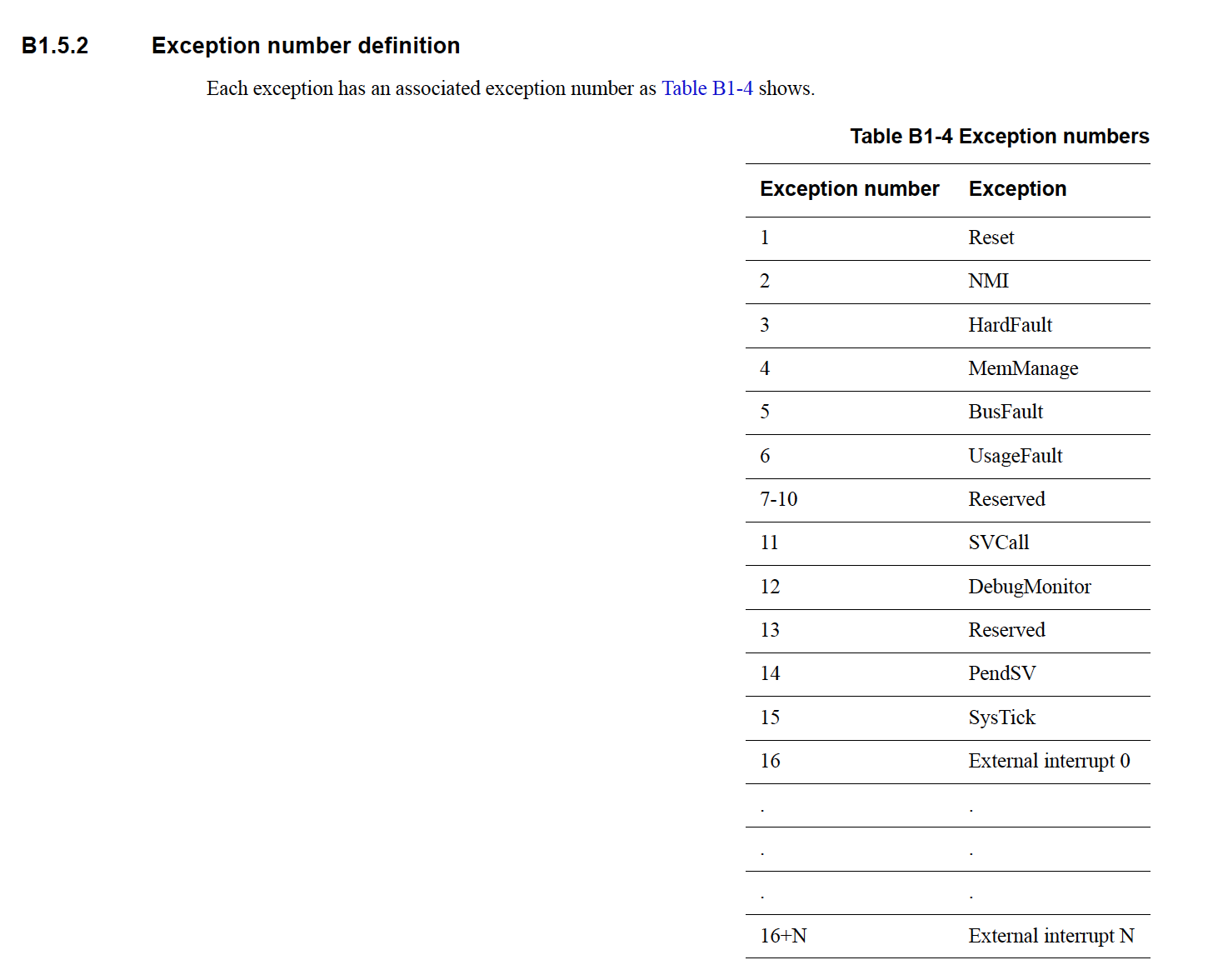
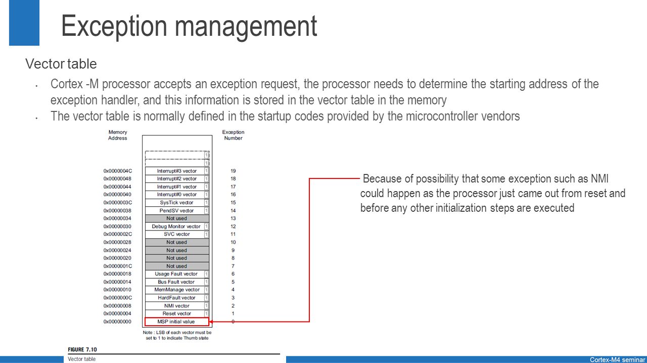
I suspect you are trying to say that the vector table in your application is relocated to 0x after boot up, and now you're trying to move it to 0x?CortexM4 r0p0 0x41 0x0 0xF 0xC24 0x0 CortexM4 r0p1 0x41 0x0 0xF 0xC24 0x1 Appendix F e129 F22 Interrupt control and state register F23 Vector table offset register Table F9 Interrupt Control and State Register (SCB>ICSR, 0xE000ED04) Bits Name Type Reset Value Description 31 NMIPENDSET R/W 0 NMI pended 28 PENDSVSET R/W 0 Write 1 toOct 14, · The figure below shows the interrupt vector table of the ARM CortexM4 microcontroller As you can see, the interrupt vector table is an array of memory addresses It contains the starting address of all exception handlers Furthermore, each interrupt/exception also has a unique interrupt number assigned to it
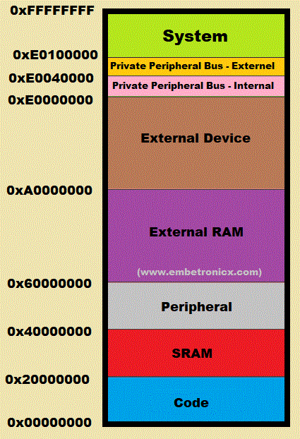


Reset Sequence In Arm Cortex M4 Boot Sequence Embetronicx


Arm Cortex M Wikipedia
Nov 11, 18 · Vector table The vector table contains the reset value of the stack pointer, and the start addresses for all exception and interrupt handlers Figure below shows the order of the CortexM4 exception and interrupt vectors in the vector table In general, the vector table is fixed at address 0x on system resetMar 01, 11 · The CortexM0 also received CortexM3 and CortexM4 features, which can be added as silicon options, such as the memory protection unit (MPU) and the vector table relocation 3 Key features of the CortexM0 core are 3Question Select The Right Options For The Following Question The Program Image In CortexM4 Contains I Vector Table Ii C Startup Routine Iii Program Code Iv C Library Code None Ii, Iii, Iv I, Ii, Iii, Iv Iii, Iv This question hasn't been answered yet Ask an expert


Basics Of Porting C Code To And Between Arm Cpus The Cortex M1 And Cortex M0 Embedded Com


Cortex M0 Devices Generic User Guide
May 10, 19 · A compact form factor is presented3 in (L) x 21 in (W) x 06 in (D), weighing 28 ozwith Cortex M4 CPU at 150 MHz and four indicator LEDs A 500mAh LithiumIon battery provides up to 400 transactions per charge in Moby/5500 It also includes multiple contact pads and USBC A whitelabel choice allows customizing branding on the frontVector Tables The address offset should be aligned to the vector table size, extended to the power of 2 For example, if there are 32 IRQ inputs, the total number of exceptions will be 32 16 (system exceptions) = 48 Extending it to the power of 2 makes it 64 (2,4,8,16,32,64) Multiplying it by 4 makes it 256 (0x100) (64 * 4 = 256)Sep 02, · As we have discussed in the last section, the vector table contains the address of the ISR routines of all interrupts and exceptions that the microcontroller supports If you check the datasheet of TM4C123G ARM Cortex M4 microcontroller, it has 15 system exceptions and 138 peripheral interrupts Peripheral interrupts are also defined as simple exceptions in literature
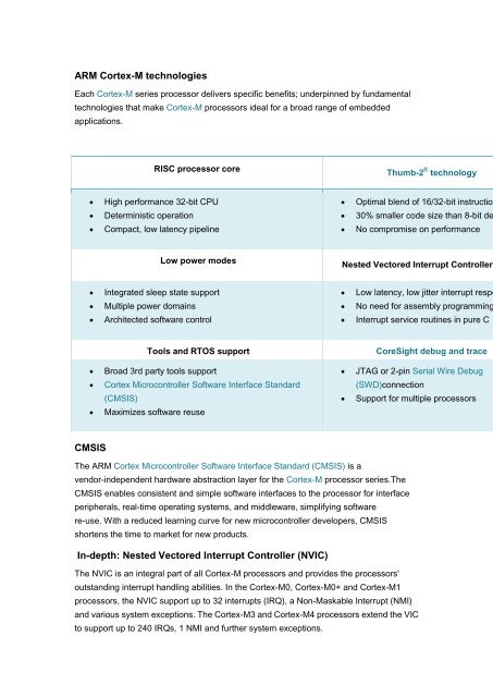


Arm Cortex M Technologies Cmsis In Depth Nested Xinnova


What Is Interrupt Vector Table In Arm Cortex M Microcontrollers
Dec 31, 14 · The ARM CortexM4 boots expects the stack pointer initialization value and the interrupt vectors on 0x SCB>VTOR, whereas SCB>VTOR is cleared at reset There is no memory at that location Flash memory starts at 0x, SRAM at 0x In order to make booting possible, the µC can map the flash or SRAM memory range to 0x TheAug 28, 16 · In the above port for CortexM4/M7, the MSP stack pointer is reset to the reset vector stack pointer This gives some extra stack bytes for the interrupt service routines Because not all CortexM0 have the vector table at address zero and there is no dedicated register to locate the initial stack pointer, this is not used for the CortexM0 portCortexM3/M4 Timer Interrupts with ARM Assembly 0 Question about the CortexM3 vector table placement Hot Network Questions Remove a merged column


A Practical Guide To Arm Cortex M Exception Handling Interrupt


List All Registers Which Will Be Saved In Stack Au Chegg Com
Oct 09, · According to the CortexM3 tech ref manual, the VTOR is defined as So we can see, it has a reset value of 0x0 So based on the above 2 criteria, the CortexM3 processor expects a vector table at the absolute address 0x0 in the Code area after reset But in my MDK uVision IDE, I see my application is placed in the IROM1 area, which starts atDifferent from previous generations of CortexM processors, such as the CortexM0/M0/M3/M4 processors, the initial vector table address on the CortexM23 and the CortexM33 processors are not fixed to address 0 Because the exact address used is defined by chip designers, you need to either check the documentation supplied, or the projectThis is information on a product in full production September DS8597 Rev 9 1/7 STM32F415xx STM32F417xx Arm® Cortex®M4 32b MCUFPU, 210DMIPS, up to 1MB Flash/1924KB RAM, crypto, USB OTG HS/FS, Ethernet, 17 TIMs, 3


A Practical Guide To Arm Cortex M Exception Handling Interrupt


Arm Cortex M Interrupts And Freertos Part 1 Mcu On Eclipse
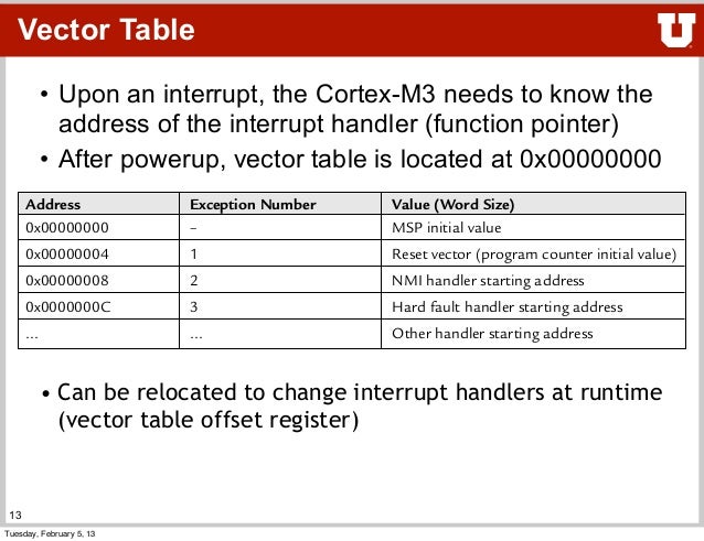
Cortex M4® Vector Table After reset, vector table is located at address 0 Each entry contains the address of the function to be executed The value in address 0x00 is used as starting address of the Main Stack Pointer (MSP) Vector table can be relocated by writing to the VTABLE register (must be aligned on a 1KB boundary) Open startup_ccsc to see vector tableAs stated by the Cortex M4 reference manual states that a system can have 0 seperate handlers within the vector table From reading through the NRF522 datasheet it states that 38 are actually used, this is also backed up within nrf52h Below can the last one can be seen FPU_IRQn = 38 /*!< 38 FPUARM CortexM4 User Guide (Interrupts, exceptions, NVIC) Sections 214, 23 – Exceptions and interrupts Interrupt vectors and vector table Interrupt masks and priorities Cortex Nested Vectored Interrupt Controller (NVIC)


Cortex M4 Technical Reference Manual


A Practical Guide To Arm Cortex M Exception Handling Interrupt
Nov 13, 18 · In some ARM Cortex architectures (I know at least the ARM CortexM0, ARM CortexM3, and ARM CortexM4 support this) there is a register located at address 0xE000ED08 called the "Vector Table Offset Register" This is a 7bit aligned address (so its 7 LSBs must be zero) which points to the location of this interrupt vector tableB How many interrupt vector numbers are reserved for internal (system) interrupts, and how many are really used?CMSISCore (CortexM) Using Interrupt Vector Remap Most CortexM processors provide VTOR register for remapping interrupt vectors The following example shows a typical use case where the interrupt vectors are copied to RAM and the SysTick_Handler is replaced #include "ARMCM3h"


Developing A Generic Hard Fault Handler For Arm Cortex M3 Cortex M4 Ppt Video Online Download


Arm Cortex M Interrupts And Freertos Part 3 Mcu On Eclipse
The STM32 Cortex®M4 MCUs and MPUs programming manual seems like a good source of information about this table For now I think it is enough to assume that when the MCU is reset, the first thing it does is jump to the reset_handler stored in the vtableNov , 19 · ARM Cortex_M4 Memory Design and Booting Sequence Lets investigate the important parts to understand how the ARM CortexM4 works from the booting time 1 Memory organization The CortexM processors have 32bit memory addressing and therefore have 4GB memory space – Store program code, including default vector tableBasics of Exceptions CortexM4 Core Peripherals › System Control Block (SCB) xSCB Registers › SysTick Timer xRegisters xConfiguration xCode Example › Nested Vectored Interrupt Controller (NVIC) xException/Interrupt Vector Table xException States xNVIC Registers


Cortex M Exception Handling Part 2 Ivan Cibrario Bertolotti
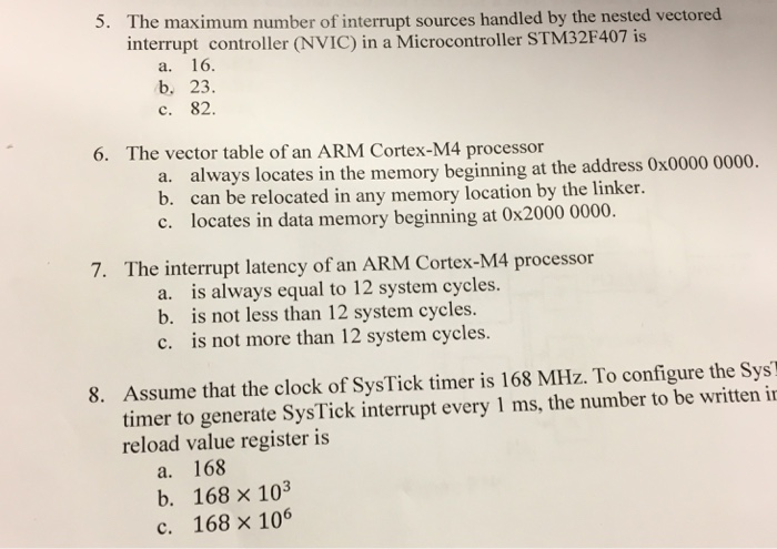


Solved The Maximum Number Of Interrupt Sources Handled By Chegg Com
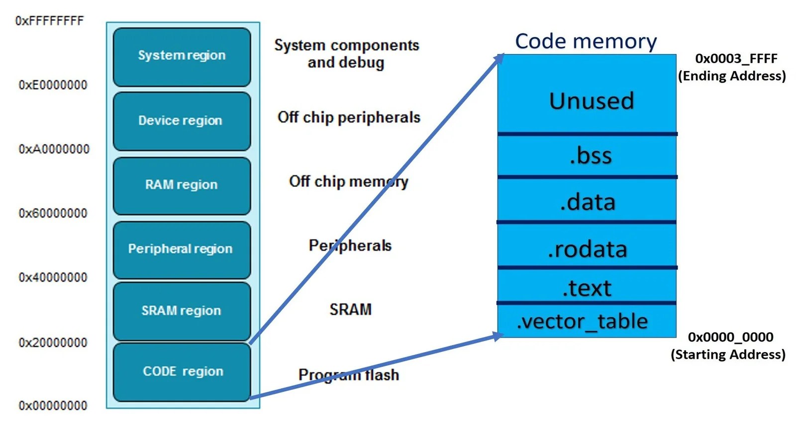
Vector Table The Vector Table defines the entry addresses of the processor exceptions and the device specific interrupts It is typically located at the beginning of the program memory, however Using Interrupt Vector Remap it can be relocated to RAMThe CortexM4 processor has an optional Memory Protection Unit (MPU) that permits control of individual regions in memory, enabling applications to utilize multiple privilege levels, separating and protecting code, data and stack on a taskbytask basisApr 25, 19 · To target low cost tools and ease of development, the interrupt architecture is designed to be simpler and straight forward The vector table in ARM Cortex M series looks like Cortex M Vector Table Typically, on poweron reset, the Vector table base address is defined to be at 0 The ARM core, up on boot up, loads the stack pointer with the value stored at offset 0


How Does Arm Find My Relocated Vector Table Stack Overflow


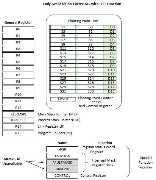
Arm Cortex M4 Programmer Model
Aug 30, 16 · Below is an example interrupt vector table for the NXP K (ARM CortexM4) with these three FreeRTOS interrupts highlighted (vPortSVCHandler, vPortPendSVHandler and vPortTickHandler)ARM Cortex M4 Architecture, ARM Assembly, startup code, Interrupt vector table, I/O Mapped I/O, Memory mapped I/O, Boot sequence, Timers, Clocks, Interrupts ARM Cortex M4 controller Overview of STM32F401RBT6 Microcontroller RaaynMini Board SpecificationsSep 24, 19 · On the ARM CortexM4 the first entry into the vector table holds the initialization value for the stackpointer, which is automatically loaded into the CPU's stackpointer register upon reset After reset, the bootloader gets started first and, if a valid user program is present, it is the bootloaders responsibility to start the user program
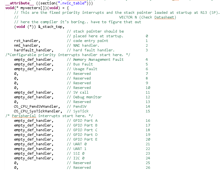


Porting Ucosiii On Cortex M4 Lm4f1xl Other Microcontrollers Forum Other Microcontrollers Ti E2e Support Forums


Bootloaders And Arm Cortex M Microcontrollers Booting The Target Application All Things Embedded
Feb 08, 16 · It is not enough to move the vector table to ram, the NVIC controller also needs to be notified Unfortunately, the CortexM0 NVIC does not provide the VTOR register, thus a manufacturer specific solution needs to be used Some examples for this can be found in the mbed repository Thus moving interrupt vectors to RAM on cortexm0 targets isChange Vector Table in cortex M4 in a persistent way Offline EA8 over 3 years ago Hello, I need to change the Vector Table but I need it to be persistent through a reset, what I'm trying to do is set a vector table duplicate as a safety measurement for reprogramming the original vector table
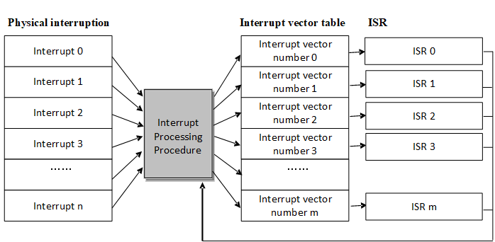


Interrupt Management Rt Thread Document Center


5 Interrupt Programming Filder Bar


Stm32f401 Problems When Relocating Vector Table On Mbed Project Mbed


Arm Cortex M Programming Guide To Memory Barrier Instructions


Solved After The System Reset The Arm Cortex M4 Processo Chegg Com


Interrupts


Terence Darwen In Depth Analysis Of An Arm Cortex M4 Program


Cortex M0 Devices Generic User Guide


الدرس ٩ Arm Cortex M4 Nested Vectored Interrupt Controller Nvic Youtube


Arm Cortex M3 Boot Process Programmer Sought


Arm Cortex M7 Devices Generic User Guide


Exceptions And Interrupts Chap 7 8 Tae Min Hwang Ppt Download


Arm Cortex M Interrupts And Freertos Part 3 Mcu On Eclipse


Cortex M Fault Segger Wiki


Cortex M4 Learning Architecture Programmer Sought


Cortex M0 Vector Table Avr Freaks
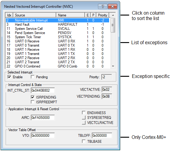


µvision User S Guide Nested Vector Interrupt Controller


Exception Vector An Overview Sciencedirect Topics


Arm Cortex M0 Silicon Labs


Reverse Engineering Of Arm Microcontrollers Rado Rc1 Security Hardware Reversing


Exception Vector An Overview Sciencedirect Topics


Cortex R5 Vector Table


Basics Of Porting C Code To And Between Arm Cpus Arm7tdmi And Cortex M0 Embedded Com


Qp C Preemptive Non Blocking Qk Kernel


What Is Nested Vector Interrupt Control Nvic


00xnor Sergey Ostrikov Cortex M4 Core Registers
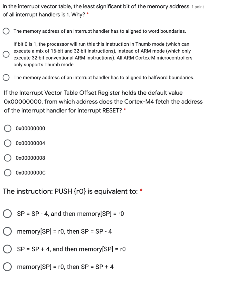


Solved In The Interrupt Vector Table The Least Significa Chegg Com


Manual Ports Armcm4 Stm32 Openblt Bootloader


Tm4c123 Tutorial Interrupt Vector Table Adding Functions To The Table Youtube


Interrupt Management Rt Thread Document Center


Arm Cortex M Interrupts And Freertos Part 1 Mcu On Eclipse


Reset Sequence In Arm Cortex M4 Boot Sequence Embetronicx


Manual Ports Armcm4 Stm32f3 Openblt Bootloader


Exceptions And Interrupts On Cortex M


Sequence Of Interrupt Processing Steps Arm Cortex M Microcontrollers


What Is Interrupt Vector Table In Arm Cortex M Microcontrollers


Interrupt Vector Table An Overview Sciencedirect Topics


Cortex M3 Devices Generic User Guide


Arm Cortex M Processor Reset Sequence


Cortex M3 Exception And Interrupt Vector Table S Programmer Sought


Basics Of Porting C Code To And Between Arm Cpus The Cortex M1 And Cortex M0 Embedded Com


Emsys Interrupts In Tm4c123gh6pm Launchpad Edwiki


Lecture 9 Interrupts Youtube


Arm Explains Good Interrupt Control For Low Power Processors


Reset Sequence In Arm Cortex M4 Boot Sequence Embetronicx


Stm32mp15 Ram Mapping Stm32mpu


5 Interrupt Programming Filder Bar
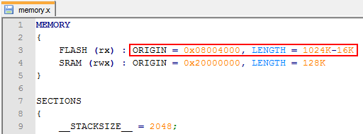


Manual Ports Armcm4 Stm32 Openblt Bootloader


Arm Cortex M Interrupts And Freertos Part 1 Mcu On Eclipse
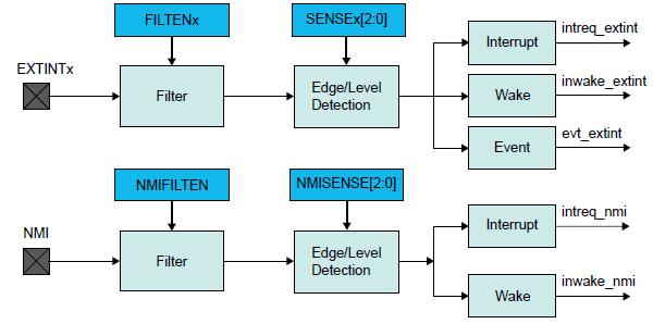


More On Fast Interrupt Handling With Cortex M4 Big Mess O Wires
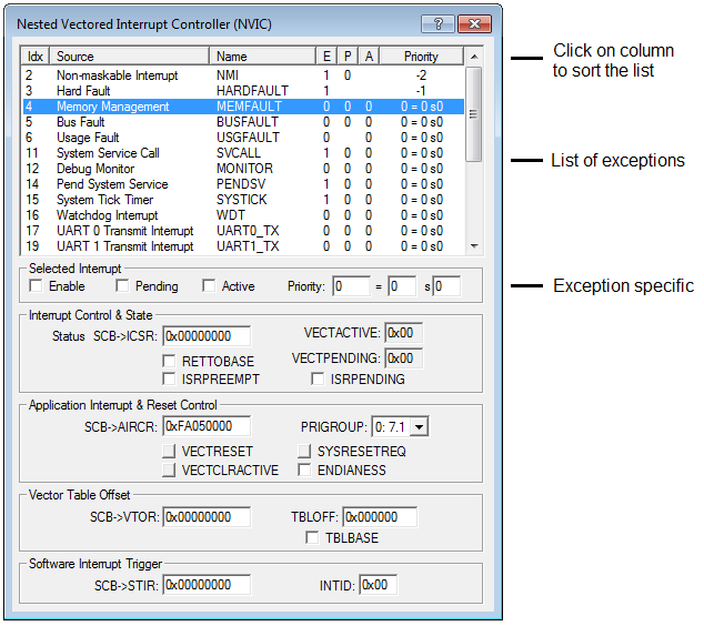


µvision User S Guide Nested Vector Interrupt Controller


Reset Sequence Of Micro Controller Embedded System Tutor


Arm Explains Good Interrupt Control For Low Power Processors
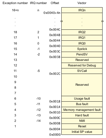


Tock Embedded Operating System Walkthrough


Chapter 6 Interrupt And Exception Programming 1 Polling


Debugging Hard Faults On Arm Cortex M Mcu On Eclipse


Arm Cortex M Wikipedia


A Deeper Look At The Stm32f4 Project Template Getting Things Started Charles Korn
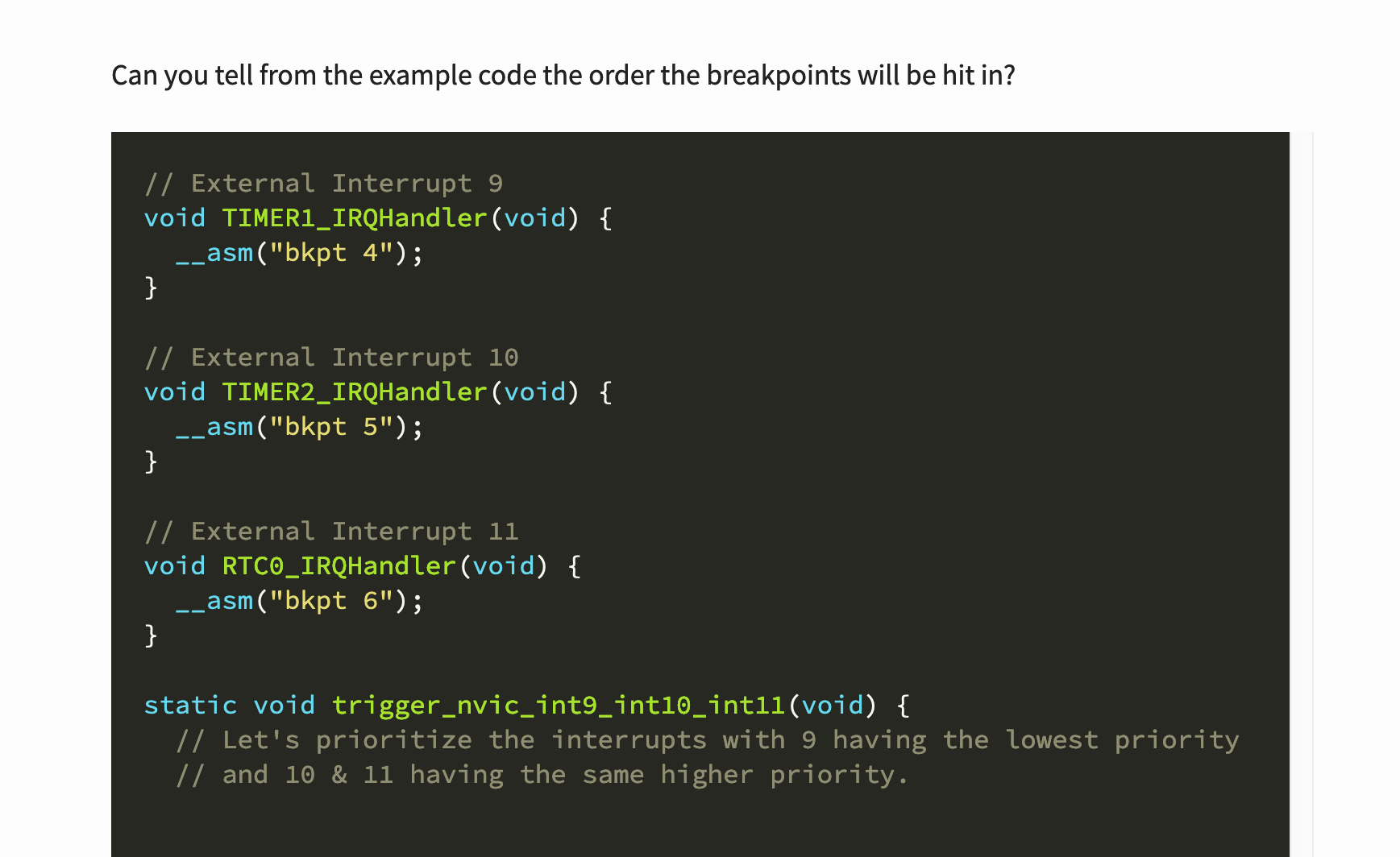


A Practical Guide To Arm Cortex M Exception Handling Interrupt


Interrupt Vector Table An Overview Sciencedirect Topics
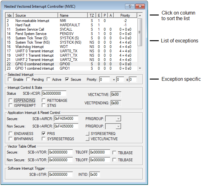


µvision User S Guide Nested Vector Interrupt Controller


Interrupt Handling In Arm Cortex M Embien Technology Blog


Cortex R5 Vector Table


Context Switching In Arm Cortex M3 M4 Wisesciencewise
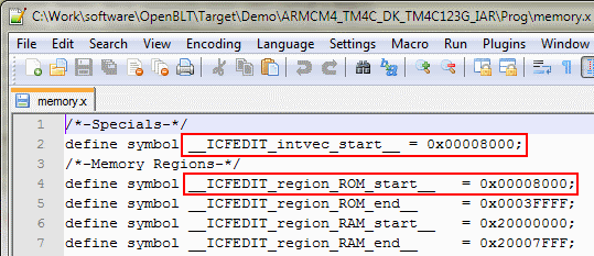


Manual Ports Armcm4 Tm4c Openblt Bootloader


Interrupt Vector Address In Program Counter Electrical Engineering Stack Exchange


Create Hardware Interrupt Block For An Arm Cortex M Based Processor Using An Interrupt Description File Matlab Simulink
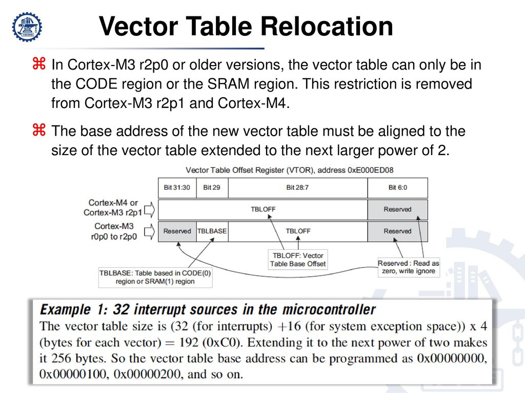


Refer To Chapter 7 8 9 In The Reference Book Ppt Download


0 件のコメント:
コメントを投稿